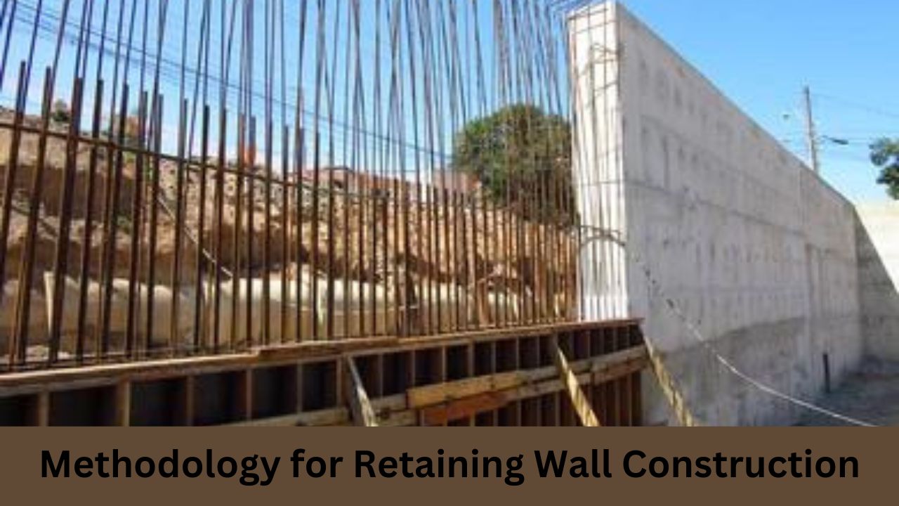
Work Methodology for Retaining Wall Construction
Purpose:
This document outlines the methodology employed for constructing RCC (Reinforced Cement Concrete) retaining wall structures.
Setting Out at Site:
The layout for the PCC (Plain Cement Concrete) leveling course is marked on the proposed location, referencing the project centerline established along the existing carriage way and approved by the Engineer. Reduced levels of the existing ground are determined jointly with the Engineer’s representative at the site and recorded for measurement purposes.
Excavation for Foundation:
Following the recording of original ground levels (OGL), excavation is carried out using excavators/JCBs up to the required level as specified in the approved drawings. Any unevenness in the bottom surface is rectified, and loose earth is manually removed to achieve a smooth finished surface.
Laying PCC Leveling Course:
Upon completion of excavation and marking of the layout, levels and layout are verified with the Engineer’s representative. Subsequently, shutters are installed to maintain line, level, and verticality. Upon approval from the Engineer’s representative, PCC is placed and leveled. The following day, shuttering is removed, and curing is initiated as per Technical Specifications.
Reinforced Cement Concreting:
a. Reinforcement:
Reinforcement steel bars are cut to specified lengths and bent to shape according to the approved bar bending schedule at the bar bending yard. These bars are transported to the site and securely tied in place as per the drawings using binding wire. Cover blocks are attached to the bottom and side faces of the reinforcement cage to ensure the required cover for the reinforcement from the concrete face, thereby preventing corrosion. Additionally, necessary reinforcement chairs are provided to support the cage.
b. Raft Concreting:
Once the reinforcement cage is assembled and secured, clean and surface-oiled shutters are installed to maintain line, level, and verticality. Any gaps in the shuttering are filled to ensure leak-proofing. A sketch of the shuttering layout is created, highlighting areas for reinforcement and service openings. Concrete is then poured onto the raft, ensuring proper compaction and finishing as per project specifications.
The detailed shuttering specifications, crucial for the construction process, have been enclosed herewith and have been presented to the engineer for trial shuttering panel approval. Prior to the commencement of concrete pouring, thorough checks will be conducted to ensure that all arrangements align with the checklist and technical specifications provided. Expansion joints will be strategically placed at approximately every 12-meter interval to accommodate potential movement and stress. Concrete will then be poured in layers and meticulously compacted utilizing needle vibrators for optimal density.
To prevent water loss in the fresh concrete, the surface will be adequately moistened before pouring. The workability of the concrete will be assessed through slump tests conducted onsite, with concrete cubes cast simultaneously for strength verification as per the Ministry of Surface Transport and Highways (MOSRT&H) specifications. Upon completion of the concrete up to the stem and starter course, shear keys will be installed on the top surface to enhance structural integrity.
During the concreting of the stem portion, shuttering will be meticulously aligned to the designated lines and verticality on the outer side, while being battered on the inner side facing the road, in accordance with the provided drawings. The shutters will be securely held in place using tie rods, clamps, M.S. pipes, adjustable props, and clamps at regular intervals. Any gaps in the shutters will be sealed with foam sheets and putty to ensure a leak-proof enclosure. Upon approval from the Inspection Engineer (IE), concrete will be placed and compacted as previously described.
The removal of all vertical shutters will be carried out 24 hours after the completion of concreting. Weep holes, spaced at 1-meter intervals in a staggered manner, will be established using 100mm diameter AC pipes with a 1:20 slope, as indicated in the drawings.
Expansion joints will be strategically placed at approximately 12-meter intervals or at the change of section, whichever is lesser, across the entire cross-section, utilizing 20mm thick bitumen impregnated boards to accommodate thermal expansion and contraction.
Curing procedures will commence the day following concreting and will continue for a period of 14 days, employing Hessian cloths or pond arrangements as specified in the technical specifications to ensure optimal strength development.
Finally, backfilling behind the walls will be executed in accordance with the specified layers outlined in the MORTH Specification, ensuring stability and longevity of the constructed structure.
Machinery Requird For Retaining Wall Construction :
Excavator:
1 unit will be deployed for excavation purposes.
Tippers:
Tippers will be made available as required for transportation needs.
Concrete Batching Plant:
1 unit of concrete batching plant will be operational for concrete mixing.
Transit Mixers:
Transit mixers will be provided as necessary for transporting concrete to the construction site.
Water Tanker:
1 water tanker will be on hand to facilitate the wetting of surfaces and other construction-related water requirements.
Needle Vibrators:
Needle vibrators will be supplied as needed for compacting concrete during the pouring process.
Survey Kit:
1 complete set of survey equipment will be utilized for precise measurements and alignment checks.
Cube Moulds:
Cube moulds will be available as required for casting concrete samples for strength testing.
Slump Test Apparatus:
1 complete set of slump test apparatus will be utilized for assessing the workability of concrete on-site.
| Join Group | Link |
|---|---|
| Construction Jobs (WhatsApp) | Join Now |
| Construction methodology (whatsapp) | Join Now |