WORK METHOD STATEMENT FOR VERTICAL PILE LOAD TEST (ROUTINE PILE)
SCOPE:
This document covers the method for conducting pile load test (Compression) to find out the Safe vertical load of pile at structure locations (Major and Minor Bridges) of our project.
| Join Group | Platform | Link |
|---|---|---|
| Construction Jobs (WhatsApp) | Join Now | |
| Construction methodology (whatsapp) | Join Now |
REFERENCES:
IS 2911-1985 Code of Practice for Design and Construction of Pile Foundation. (Part 4) Load test on Piles.
MANPOWER & EQUIPMENTS DETAILS:
- Skilled Labour – As required
- Engineer/Technician – As required
- Excavator/Dozer/Grader – As required
- Loaded truck for estimated load reaction
- Hydraulic Jack of required capacity with calibrated pressure gauge
- Dial gauges having 50mm travel with accuracy of 0.01mm
- Datum bar of sufficient length to fix up the dial gauges by using magnetic base.
- Miscellaneous items like packing plates etc.
PROCEDURES:
1. Test Load
The Safe Vertical Load at cut off level= VL
Maximum Test load = 2.5 VL
The initial load test has to be carried out to maximum test load of 2.5 times the design capacity as per IS: 2911, Part-IV, (APPENDIX-A). The test will be carried out by cyclic method up to 1.5 times the design load and thereafter with normal loading up to the maximum test load.
The Kent ledge load shall be at least 25% extra over the maximum test load on the pile, i.e. 1.25 x (2.5 VL).
2. Cyclic Load Test on Piles
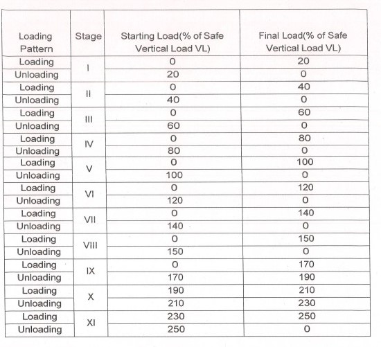
The initial cyclic load test shall be conducted by applying a series of vertical loads on the test pile. Alternate loading and unloading shall be carried out at each stage as presented in Table 6 -1.
The load shall be applied by means of hydraulic jacks reacting against a symmetrically erected loading platform which shall be preloaded to not less than 1.25 times the maximum test load on the pile. The hydraulic jack shall be of adequate capacity and shall have a pressure gauge and remote control pump.
The pile to be tested shall be chipped and dressed to a well-leveled surface. It is important that reinforcing bars of the pile do not project beyond the top surface of the leveled pile top.
A circular steel plate of suitable thickness and size of the plate more than or equal to the dia. of the pile placed a fine layer of sand spread over the top of the pile.
One or multiple jacks shall be used, depending upon the capacity of the jacks and as per the ultimate test load. As per the site condition required steel plates shall be inserted between the gap formed by the top of the plate resting on the pile and the lower flange of the main R.S.J.’s of the load platform. The jacks should preferably be connected and operated by one pump. Hydraulic jacks shall be selected such that the maximum hydraulic oil pressure should not exceed the capacity of the pressure pump.
The testing agency shall submit calibration charts showing the correctness of the calibration of the pressure gauges and the jacks before use. All jacks will be fit with the locking devices. Another plate of suitable thickness shall be placed over the ram of the jack, which is later raised by operating the hydraulic pump so that the plate on the top of the ram butts against the bottom flange of the main R.S.J’s of the platform.
Reading of settlement and rebound shall be recorded with the help of min. two dial gauges of 0.01 mm sensitivity and resting on diametrically opposite ends of the pile cap.
The dial gauges shall be fixed to a support which is at least 3 times the diameter of the pile or a minimum of 1.50 m away clear from the edge of pile. Readings on the dial gauges are to be observed immediately before and after application of loads, and immediately before and after release of loads. The loading shall be applied in increments of 20% of the estimated safe load. The sequence of loading and unloading shall be as described below.
Table
Loading and Unloading Sequence for the Vertical Load Test Pile
Each stage of loading shall be maintained until any of the following criteria occurs first:
1.The rate of displacement/movement of the pile top is 0.1 mm in first 30 minutes.
2.The rate of displacement/movement of the pile top is 0.2 mm in first 60 minutes.
3.Till 2 hours.
During the unloading stages, the load on the pile shall be maintained for aminimum of 15 minutes and the subsequent elastic rebound in the pile shall be measured accurately by dial gauges.
The final load shall be maintained for 24 hrs and the corresponding settlement shall be observed. Rebounding shall be recorded after the entire load is released. The pile test data shall be suitably presented by curves drawn between variables namely load and displacement and safe loads shown on the graphs including fieldobservations.
The readings for settlement and rebound shall be entered in the following formats:
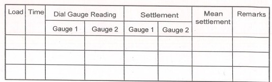
The dial gauge readings shall be taken at every interval of loading & unloading.
Plant and Equipment
All temporary work plant, equipment, kentledge & supply of the loading arrangement along with all necessary instruments for measurements of loads, deflection etc. shall be provided by the testing agency. The equipment provided shall be capable to apply slowly and smoothly and to maintain the load at any required value. The load shall be measured by a single load cell / proving ring or a similar device calibrated in divisions not exceeding 5 t. All increments of load shall be maintained to 5 t. A spherical seating of appropriate size shall be used to avoid eccentric loading.
Records
- The testing agency shall keep the following records of the tests.
- Make and specification of the jacks, pressure gauges and dial gauges.
- Calibration of pressure gauges and dial gauges.
- Description of location and identification marks of piles.
- The table of load settlement data.
- A plot of the load settlement curve indicating the load for 12 mm.
- Settlement and that for 10% of pile diameter, if achieved.
Acceptance Criteria
The Safe Capacity of Piles is considered to be the least of the following as per IS: 2911, (Part 4)
2/3rd of the load corresponding to 12 mm settlement.
50% of the load corresponding to a settlement of 10% of pile diameter.
INSPECTION & QUALITY CONTROL:
Test Observations shall be done at prescribed time and calculations shall be done to find out the Safe Vertical load. Then the reports shall be submitted to IE and our designer’s review.
SAFETY:
The safety arrangements shall be made as per the safety plan and procedures.
CONCLUSION:
The Vertical pile load test shall be proceeded further as per above mentioned procedures in accordance with the specification requirements on test and working piles.