Introduction of Plate Load Test :
The Plate Load Test serves as a crucial field test to ascertain both the ultimate bearing capacity of soil and the expected settlement under a given load. This test involves the systematic loading of a steel plate positioned at the foundation level, with corresponding settlements recorded for each load increment. The load is gradually increased until the plate experiences a rapid sinking rate. The ratio of the total load on the plate at this stage to the area of the steel plate provides the ultimate bearing capacity of the soil. To determine the Safe Bearing Capacity of the soil, the ultimate bearing capacity is divided by a suitable factor of safety, typically ranging from 2 to 3.
The Plate Load Test is categorized into several components, including its objectives, the required apparatus, and the step-by-step procedure. The objective of this test is to generate a load-settlement curve for a specific soil depth, aiding in the estimation of the ultimate bearing capacity of a foundation.
Apparatus Use PLT Test :
- Test Plate size (300mm, 450mm, 600mm, or 750mm)
- Hydraulic jack
- Hydraulic pump
- Load gauge
- 2 dial gauges (with sensitivity of 0.01 mm and a travel of 25mm)
- Loading columns
- Dial gauge supporting channel
- Dial gauge supporting channels
- Magnetic bases for dial gauges
- Loaded vehicle
- Spirit level
Procedure of plate load test :
- Excavate a test pit at the proposed foundation site, with a width five times the size of the test plate and a depth equal to the foundation depth.
- Position the loaded vehicle over the test pit, ensuring the vertical line through its center of gravity passes through the center of the pit’s base.
- Center the plate at the pit’s base, ensuring a level and horizontal ground surface beneath it.
- Set up the hydraulic jack to push against the loaded vehicle, ensuring a stable loading platform.
- Place two dial gauges diagonally to record plate settlements, supported by stable bases.
- Position the dial gauges with their plungers at the beginning of rebound.
- Apply a seating load of 70g/cm2 and note the initial dial gauge reading.
- Gradually apply load increments through the hydraulic jack, recording settlements at specified intervals.
- Continue load increments until reaching the maximum load (1.5 times the estimated ultimate load or 3 times the proposed allowable bearing pressure).
- Document settlements in a tabular form.
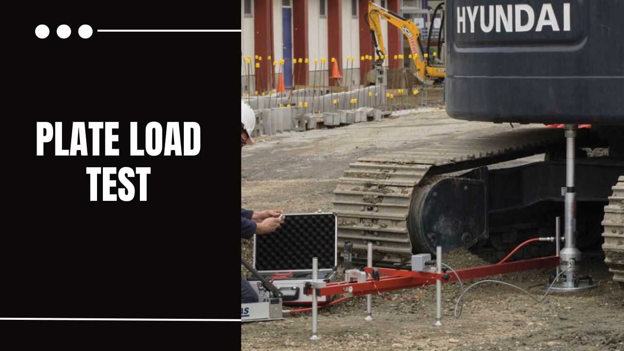
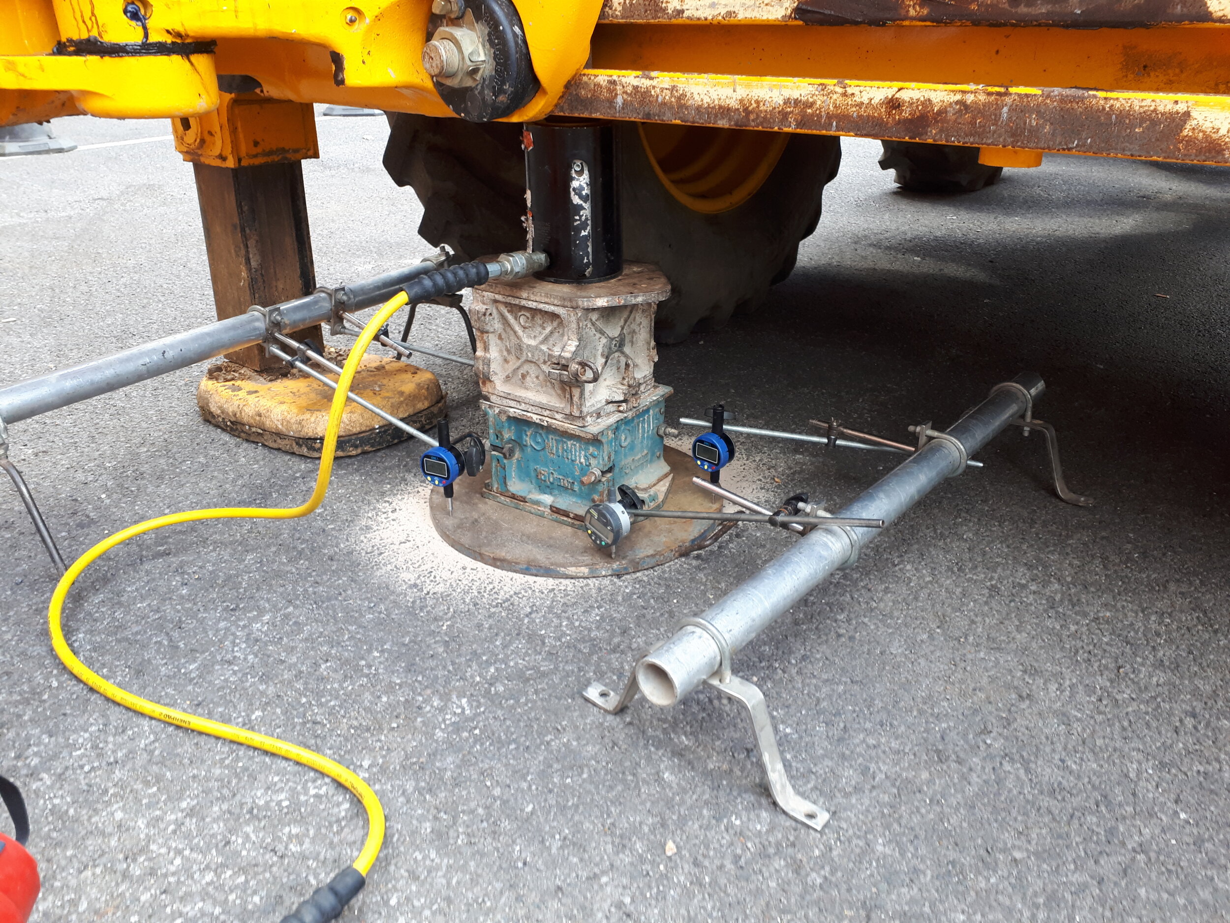
Test Setup of plt machine:
Refer to Figure for the illustration of the test setup, including the plate, loading column, hydraulic jack, counterweight, pressure, and settlement gauge.
Calculation of plate load test :
The Safe Bearing Capacity is calculated by dividing the ultimate bearing capacity by a factor of safety (2 to 3). This value is considered based on the criterion of shear failure. The permissible settlement for different types of footings and structures can be obtained from load-settlement curves and calculated using the formula:

References of plate load test:
IS: 1888 : 1982: “Method of Load Test on Soil.”