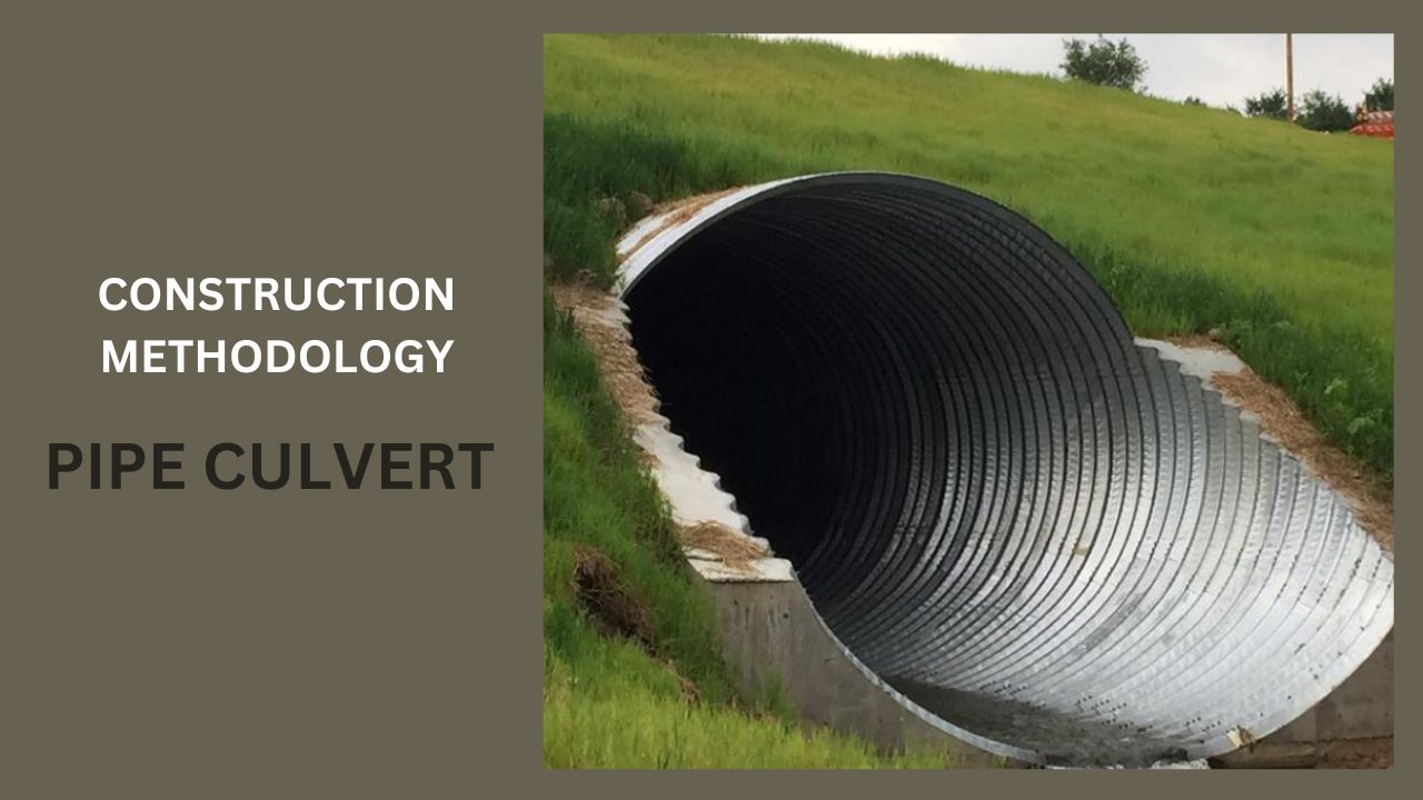
1.0 GENERAL DESCRIPTION
The work comprises the supply and installation of reinforced concrete pipe culverts, inclusive of excavation of excavation, backfilling, bedding all in accordance with the contract specification and the details shown on the drawings.
2.0 MATERIALS
2.1 Reinforcement concrete pipes shall be NP-4 type and conform to the requirements or otherwise specified and shall be supplied by manufactures approved by the Engineer.
2.2 A ratio of 1:2 cement mortar for jointing of reinforced concrete pipe shall conform to the requirement of the contract specification.
3.0 EQUIPMENT
3.1 Concrete weigh batching plant of minimum capacity 18m3/Hr.
3.2 Crane (5 T capacity) and bucket system for placing concrete.
3.3 Transit Truck mixer and dumpers.
3.4 Needle Vibrators (Electrical or petrol drive units)
3.5 Crane 5T capacity for handling shuttering, reinforcement and materials.
4.0 CONSTRUCTION METHODS OF PIPE CULVERT
4.1 The quality of materials used in the manufacture of precast concrete pipes shall be subject to inspection and approval by the engineer. Pipes shall comply with the specified requirement and shall not exhibit any of the following defects at the time of installation. Approval forms shall be submitted for facilitating approval of each stage of work.
i. Major fractures or cracks, Defects that indicate imperfect proportioning of the constituent materials.
Surface defects indicating honey combing or open texture.
ii. Damaged ends or distortion which would prevent making of a satisfactory joint.
4.2 Pipe culverts which are to be constructed at excising at existing ground level and under an existing embankment shall have a trench cut excavated to receive the culvert down to the levels shown on the drawing.
In case of high embankments with height of fill more than 3 times the External die of pipe, embankment shall be built first up to one die above the elevation of the top and to width on each side equal to five times the die of pipe, after which the trench can be cut to lay pipes.
The width on either side of the pipe shall be a min 15 cm of ¼ die of pipe whichever is greater, but not exceeding 1/3 die-of pipe. The sides of trench should be a nearly vertical as possible.
4.3 In areas of soft, unsuitable soil where the removal of unsuitable material is indicated in the drawings or as directed by the engineer, Culverts are to be constructed at the existing groindlenel prior to the construction of an embankment and such cases the procedure shall be as folliws: The unsuitable material shall be excavated to such length, width and depth directed by the Engineer. It shall be back filled in specified layers with approved granola fill of the same standard as specified for granular bedding material, and shall be compacted to the same specified standareds. The prepared surface shall provide a firm foundation of uniform density throughout the length of the culvert to receive the pipe bedding.
4.4 Culverts which are to be constructed below existing ground level shall be laid in a trench excavated from that level. Excavation of the trench shall be to the width shown on the drawings, the trench bottom shall be trimmed true to line and level and soft sport and any over break dealt with as described in the contract specification. Particular care shall be taken where excavation is in rock to ensure that there is a minimum cushion of 200 mm layer of approved compacted earth below the pipe.
4.5 Trenches shall be kept free from water until pipes are laid and joints have hardened.
4.6 Pipes shall not be laid until the foundation and the Engineer has approved the pipes class, size and length called for at each location.
4.7 Concrete pipes shall be laid true to line, level, each pipe being separately Aligned pipes shall be laid from the outle and proceeded towards inlet. Prior to joining, jointing surfaces shall be cleaned of all contaminants. In pipes with bell month the spigot of each pipe shall be inserted concentrically in the socket of the one previously laid, and the pipe adjusted and fixed in its correct position with the spigot accurately centred in the socket. Care shall be taken to see that the sealant is adequately compressed to seal the joint. Alternatively joints can be filled with Cm 1.2
4.8 For all culverts constructed in trench, back filling is done with suitable Material or bedding material as specified and placed in even layers equally on either side of the pipe to a height of 300 mm above the crown of the pipe. This shall be placed in layers not exceeding 150mm thick and dull and duly compacted. Where culverts are constructed in height embankments the surround material shall be placed and compacted in layers not exceeding 150mmbrougth up evenly on both sides of the pipe to a height of 1000mm above the crown of the pipe. Above this level suitable material shall be placed in accordance with the contract specification.
4.9 Heavy earth moving and compacting equipment shall not be permitted to Cross the pipe line until a minimum of 600mm of back fill, sub base or base course has been placed and compacted over the crown of the pipes or otherwise specified.
SITE RECORDS
The Site Engineers in charge of works, shall ensure that the site supervisors continuously supervisor and observe the construction of the culvert and maintain the daily site diary sheets each day. The daily site diary sheets shell record the following information’s.
a. Location of the works.
b. Type of works and operations.
C. Plant and equipment’s used on site.
d. Sub-contractors labour resources, if any.
e. Total length of culvert laid at each location.
f. Weather condition and details of delays, if any.
The Site Engineers shall ensure that the total length of culvert laid at each location is measured and recorded in the presence of the Engineer’s representative, immediately after completion of the works.

