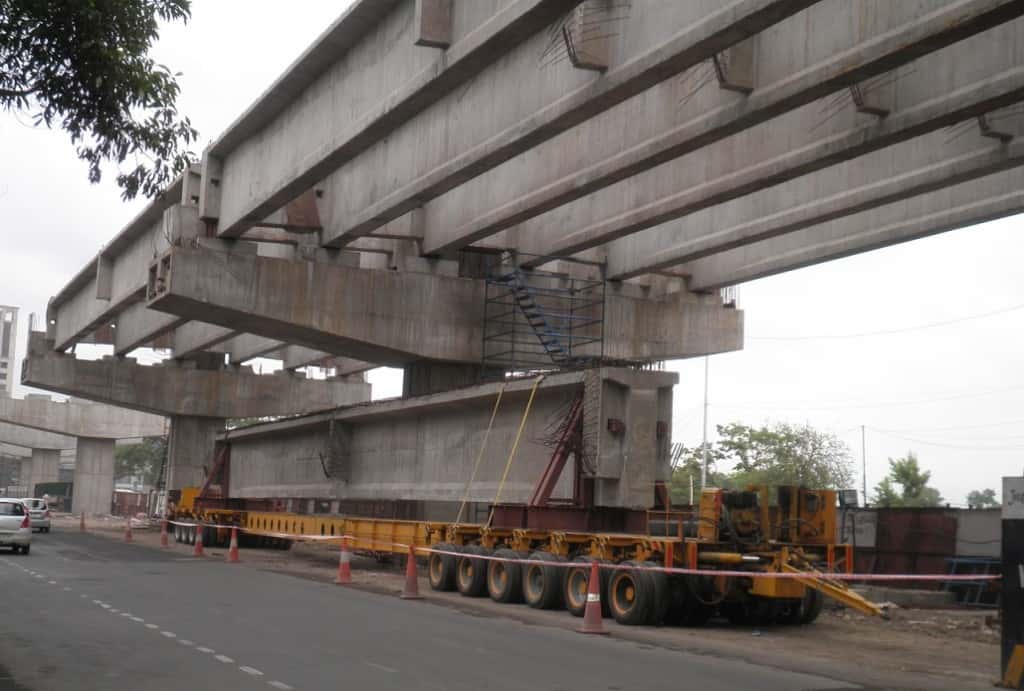
We are pleased to announce that the construction of a new flyover in our area has begun today. Here are the details of the flyover drawing:
Flyover Length: 120m
Span Duration: 30m

Overview of Flyover Drawing:
- Type: Flyover
- Design: Prestressed Concrete Girder
- Specifications: Designed to accommodate various types of vehicles including two-wheeled, four-lane Class A, seven-wheeled with lanes of Class A, and special purpose vehicles.
- Material Grade: Steel: Fe-550D (as per IS: 1786)
- Expansion Joints: Strip seal type, conforming to IRC SP:69-2005
- Concrete Details: M50 for PSC Precast I Girder, M40 for Deck Slab
- Weep Holes: Provided in a staggered manner in return wall and abutments above ground level/LWL.
- Backfilling: Earth conforming to Appendix 6 of IRC 78-2000.
- Water Quality: Concreting and curing water conforming to IRC 112.
- Wearing Coat: Consists of Bituminous Concrete (50mm) and 3mm Waterproof Membrane.
Important Notes:
- Dimensions: All dimensions are in millimeters unless otherwise specified.
- Levels: All levels are in meters unless otherwise stated.
- Verification: Ensure all levels are verified before execution at the site.
- Load Capacity: Refer to corresponding drawings for actual designed loads.
- Prestressing: Detailed prestressing instructions are provided for adherence.
Flyover Drawing Documents:
| Flyover GD Drawing PDF |
|---|
| Flyover Abutment Drawing PDF |
| Flyover Pier Drawing PDF |
| Flyover Super Structure Drawing PDF |
| Bar Bending Schedule PDF Abutment & Pier |
Safety and Compliance:
- Adherence to safety protocols and regulatory compliance is mandatory throughout the construction process.
- Any deviations or discrepancies from the specified design or standards should be promptly reported to the designated authorities for resolution.
Conclusion:
We are dedicated to delivering a high-quality flyover that meets safety standards and effectively serves the transportation needs of our community. Let us embark on this construction journey together, ensuring excellence.
